Description AC7-02: Difference between revisions
| Line 41: | Line 41: | ||
The Schmidt’s geometry was supplemented with the oral cavity described in the following paragraph. | The Schmidt’s geometry was supplemented with the oral cavity described in the following paragraph. | ||
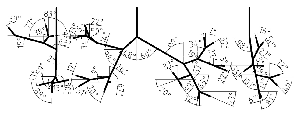
[[File:angles.png|center|200px |Figure 1: Branching angles of tracheobronchial airways.]] | [[File:angles.png|center|200px|frame|Figure 1: Branching angles of tracheobronchial airways.]] | ||
===The oral cavity=== | ===The oral cavity=== | ||
Revision as of 20:47, 15 May 2020
Airflow in the human upper airways
Application Challenge AC7-02 © copyright ERCOFTAC 2020
Description
Introduction
In the current application challenge (AC), in vitro velocity measurements using particle image velocimetry (PIV), Large Eddy Simulations (LES) and Reynolds-Averaged Navier-Stokes (RANS) have been conducted in a human-based model of the upper airways (shown in figure 3). This AC is a direct follow up of the application challenge “AC7-01:Aerosol deposition in the human upper airways” and provides the corresponding flow velocity data. The investigations were performed for steady-state inhalation at a flow rate of 60 L/min. The flow conditions at these flowrates are in the turbulent regime. LES and RANS simulations were carried out in the same geometry and under the same ventilation conditions. The methods and results described in the present application challenge are mainly adopted from Janke et al. (2019) (experimental part) and Koullapis et al. (2018) (numerical part).
Relevance to Industrial Sector
Aerosolized delivery of drugs to the lungs is used to treat a number of respiratory diseases. Regional deposition effects play a critical role in applications where targeted drug delivery is needed in order to maximize efficacy and minimize side-effects. Quantifying regional deposition is therefore important in assessing and optimizing treatment. Validated computational fluid-particle dynamics methods offer a powerful tool to predict airflow and localized deposition in the respiratory airways, in order to further our understanding of the flow and aerosol dynamics, and test and optimize inhaler therapies. However, accurate and efficient numerical simulations of the respiratory airways pose a challenge due to the complexities associated with the airway geometry, the flow dynamics and the aerosol physics. Numerical studies conducted to date have adopted a variety of computational techniques, a range of airway geometries varying in complexity, and differing assumptions on the flow and aerosol physics. In addition to the wide variability in the modelling approaches, validation of CFD methods in the respiratory airways is limited. The objective of the current application challenge is to present a benchmark case that can be used for the validation of computational tools intended for regional deposition studies in the upper airways. In this part, in vitro velocity measurements in a complex realistic geometry are provided at various inhalation flow rates. CFD (LES and RANS) results are then compared against the measured data and best practice guidelines for accurate numerical predictions of airflow inside the human upper airways are suggested.
Design or Assessment Parameters
Mean in-plane velocity magnitudes and turbulent kinetic energy fields were measured and numerically predicted at three planes within a realistic model of the human upper airways. The procedure to calculate these fields in the PIV experiments is described in section 2.3.
Flow Domain Geometry
Digital reference model of bronchial tree
The digital reference model of Schmidt et al. (2004) served as a basis for the new model. The original geometry was produced by high resolution computerized tomography (HRCT) of an excised lung of an adult male free of pathological alterations. Their model development uses special image processing algorithms for the segmentation and delineation of the bronchi. The model does not include upper airways, it begins with trachea and spans down to the 17th generation of branching. Our model currently extends only to the seventh bifurcation, but geometry through the 17th Horsfield order is available and could be used for a more complete airway model. The measured branching angles are shown in Figure 1 (Lizal et al., 2012). The Schmidt’s geometry was supplemented with the oral cavity described in the following paragraph.
The oral cavity
The upper part of the Lovelace Respiratory Research Institute’s (LRRI) ‘’A model‘’ (Zhou & Cheng, 2005) was used to construct the current model. The anterior oral cavity was molded from in vivo dental impression of a living Caucasian male at approximately 50 percent of the full opening (Lizal et al., 2015). The wax model provided by LRRI was scanned by an Atos (GOM) device, converted to STL format, and concatenated with our original model at the trachea (Figure 3). The dimensions of current models are summarized in Tables 1 and 2. In Table 2, the dimensions of the current model are compared to previously published model geometries.
Manufacturing of the physical model for flow measurements
Limitations of the model
Flow Physics and Fluid Dynamics Data
Contributed by: P. Koullapisa —
aDepartment of Mechanical and Manufacturing Engineering, University of Cyprus, Nicosia, Cyprus
© copyright ERCOFTAC 2020
