Abstr:Confined double annular jet
Description Test Case CFD Simulations Evaluation Quality Review Best Practice Advice Related UFRs
Application Area 2: Combustion
Application Challenge AC2-07
Abstract
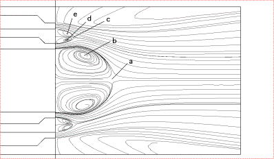
The Application Challenge, "Confined Double Annular Jet" proposed by VUB, Belgium, is an axisymmetric double annular flow field generated by a burner, and discharging into a confined combustion chamber (see Fig. 1 below). The flow is studied in cold conditions, and in a nozzle region going from the nozzle to 1.5 diameters downstream. The resulting mean flow is axisymmetric; it can be qualified as a complex turbulent flow. The flow possesses a central vortex and two small toroidal contra-rotating vortices. There are stagnation points and lines, mixing regions and recirculation regions (see Fig. 2 below). This is thus a good AC, since there is a relatively simple geometry (axisymmetric), and the ability of CFD codes to reproduce several properties of complex flows can be tested.
The available experiments are the following:
Experimental data #1: Air flow with a 156 mm largest diameter jet, with a maximum velocity of 6.3 m/s, corresponding to a Reynolds number of . For this flow, 2D LDV data have been recorded, providing axial and radial mean velocities, axial and radial turbulence intensities and Reynolds stress. The data are provided on a dense experimental grid composed of 36 sections, each of which possessing 100 to 200 measurement points.
Experimental data #2: The flow field, generated in the combustion chamber model by water flow through the model, is measured with a 2D2C PIV system. A total of 271 instantaneous vector fields, each containing 5040 vectors in the near nozzle region, are presented. The flow rate through the burner was 4.09x10⁻⁵ m3/s giving a Reynolds number 180, based on nozzle opening dr (2 mm) and mean exit velocity Ue (0.09 m/s). This produces a central toroidal vortex in the transitional state.
Industrial devices in fluid engineering quite often involve complex turbulent flows. This is the case for example in turbine engines, industrial furnaces, combustors and burners. Industrial burners are designed to generate stationary combustion in a confined chamber, with desired values of velocity, temperature and species concentrations at the exit of the combustion chamber. In general, they consist of several nozzles arranged around an axis in a confined space. The fuel and the oxidizer (usually air) issue out of the nozzles and these jets mix by turbulent diffusion. Burners are often installed to destroy pollutants gases resulting from industrial activities, before releasing them in the atmosphere.
Since international norms in matter of pollution are getting more and more binding, it is important to be able to modify the burner in order to minimize the emission of pollutant species. Since burners are usually designed and modified empirically by the manufacturer, the modifications cannot be optimal. It is therefore important to be able to better understand the flow field and the combustion process associated to burners. The turbulent diffusion of species is faster than the combustion process, so that the first step to understand a burner is to study the flow field in cold conditions. It is essential to understand the behavior of the various jets and their interaction with the neighbouring jets and surrounding flows to successfully predict the performance of the device.
The test case provided here contains a complete database in axisymmetric conditions, providing the mean velocity field, turbulence intensity, Reynolds stress components, corresponding to 2 components of the mean velocity and 4 non-zero components of the Reynolds stress tensor. This test-case can thus be used to test the validity of CFD to reproduce the complex flow created by confined annular jets. For the nozzle region (up to 1.5 diameters) this AC is well understood, in terms of data available and overall quality (for experimental data #1, globally less than 2% axisymmetric errors).
The position of some particular points can be used as assessment parameters to judge the validity of CFD computations (more specific comparisons can be done later). Several locations have been selected below, as shown in Figure 2.
Contributors: Charles Hirsch; Francois G. Schmitt - Vrije Universiteit Brussel


