UFR 2-04 References
Flow around (airfoils and) blades (subsonic)
Underlying Flow Regime 2-04 © copyright ERCOFTAC 2004
References
Biswas D., and Fukuyama, Y., (1994), “Calculation of Transitional Boundary Layers with an Improved Low-Reynolds-Number Version of k–ε Turbulence Model,” ASME J. Turbomachinery, Vol. 116, pp. 765-773.
Biswas D., Iwasaki, H., and Ishizuka, M., (1997), “Numerical Analysis of Two-Dimensional Compressible Viscous Flow in Turbomachinery Cascades Using an Improved k-ε Turbulence Model”, ASME Paper 97-GT-417.
Craft, T. J., Launder, B. E., and Suga, K., (1993), “Extending the Applicability of Eddy viscosity Models through the Use of Deformation Invariants and Non-Linear Elements,” Proc. 5th Int. Symp. Refined Flow Modelling and Turbulent Measurements, p. 125.
Deutsch, S., and Zierke, W. C., (1987), “The Measurement of Boundary Layers on a Compressor Blade in Cascade: Part 1 - A Unique Experimental Facility,” ASME Paper 87-GT-248.
Deutsch, S., and Zierke, W. C., (1987), “The Measurement of Boundary Layers on a Compressor Blade in Cascade: Part 2 - Suction Surface Boundary Layers,” ASME Paper 87-GT-249.
Deutsch, S., and Zierke, W. C., (1987), “The Measurement of Boundary Layers on a Compressor Blade in Cascade: Part 3 - Pressure Surface Boundary Layers and the Near Wake,” ASME Paper 87-GT-250.
Elazar, Y., and Shreeve, R. P., (1990), “Viscous Flow in a Controlled Diffusion Compressor Cascade With Increasing Incidence,” ASME J. Turbomachinery, Vol. 112, pp. 256-266.
Emmons, H. W., (1951), “The Laminar-Turbulent Transition in a Boundary Layer — Part I,” J. Aerospace Science, Vol. 18, No. 7, pp. 490-498.
Kang, S.-H., Lik, J. S., Choi M.-R., and Kim, K.-Y., (1995), “Numerical Calculations of the Turbulent Flow Through a Controlled Diffusion Compressor Cascade,” ASME J. Turbomachinery, Vol. 117, pp. 223-230.
Launder, B. E., and Sharma, B. I., (1974), “Application of the Energy-Dissipation Model of Turbulence to the Calculation of Flows Near a Spinning Disk,” Letters Heat Mass Transfer, Vol. 1, pp. 131-138.
Leonard, B. P., (1979), “A Stable and Accurate Convective Modelling Procedure Based on Quadratic Upstream Interpolation,” Comp. Meth. Applied Mech. Engineering, Vol. 19, pp. 59-98.
Lien, F. S., Chen, W. L., and Leschziner, M. A., (1996), “A Multiblock Implementation of a Non-Orthogonal, Collocated Finite Volume Algorithm for Complex Turbulent Flows,” Int. J. Num. Methods Fluids, Vol. 23, pp. 567-588.
Lien, F. S., and Leschziner, M. A., (1993), “Computational Modelling of 3D Turbulent flow in S-Diffuser and Transition Ducts,” Letters Heat Mass Transfer, Vol. 131.
Mayle, R. E., (1991), “The Role of Laminar-Turbulent Transition in Gas Turbine Engines,” ASME J. Turbomachinery, Vol. 113, pp. 509 – 537.
Menter, F. R., (1992), “Improved Two-Equation k–![]() NASA TM 103975.
NASA TM 103975.
Schmidt, R. C., and Patankar, S. V., (1991), “Simulating Boundary Layer Transition with Low-Reynolds-Number k–![]() Turbulence Models. I - An Evaluation of Prediction Characteristics. II - An Approach to Improving the Predictions,” ASME J. Turbomachinery, Vol. 113, pp. 10-26.
Turbulence Models. I - An Evaluation of Prediction Characteristics. II - An Approach to Improving the Predictions,” ASME J. Turbomachinery, Vol. 113, pp. 10-26.
Shreeve, R. P., Elazar, Y., Dreon, J. W., and Baydar, A., (1991), “Wake Measurements and Loss Evaluation in a Controlled Diffusion Cascade,” ASME J. Turbomachinery, Vol. 113, pp. 591-599.
Steelant, J., and Dick, E., (1996), “Modelling of Bypass Transition with Conditioned Navier-Stokes Equations Coupled to an Intermittency Transport Equation,” Int. J. Num. Methods Fluids, Vol. 23, pp. 193 – 220.
Suzen, Y. B., and Huang, P. G., (2000), “Modelling of Flow Transition Using an Intermittency Transport Equation,” ASME J. Fluids Engineering, Vol. 122, pp.273-284.
Tselepidakis, D. P., (1996), “Modelling and Prediction of the Laminar Leading-Edge Separation and Transition in a Blade-Cascade Flow,” ASME Paper 96-GT-411.
Zierke, W. C., and Deutsch, S., (1989), ‘The Measurement of Boundary Layers on a Compressor Blade in Cascade: Part 4 - Flow Fields for Incidence Angles of -1.5 and -8.5 Degrees,’ ASME Paper 89-GT-71, also ASME J. Turbomachinery, Vol. 112, pp. 241-255 (1990).
Wilcox, D. C., (1994), “Simulation of Transition with a Two-Equation Turbulence Model,” AIAA J., Vol. 32, p. 247.
 |
|
|
 |
 |
|
Figure 2: Schematic of the cascade wind tunnel (from Elazar and Shreeve, 1990). |
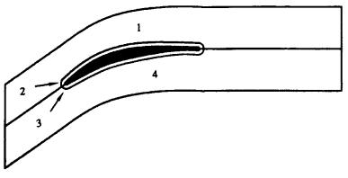
Figure 3: Cascade passage geometry and LDV measuring stations (from Elazar and Shreeve, 1990). |
 |
 |
 |
 |
|
Figure 5: Pressure coefficient distributions along the blade chord. Clock-wise from upper right: Lien et al. (1996), Tselepidakis (1996), Biswas et al. (1997) and Kang et al. (1995). | |
 |
 |
|
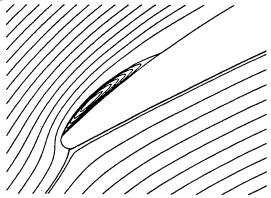
Figure 6: Stream function contours at the leading edge. Right: Tselepidakis (1996), left: Kang et al. (1995). | |
 |
 |
|
Figure 7: Pressure loss coefficient (left) and exit flow angle (right) distributions (from Kang et al., 1995). | |
 |
|
Figure 8: Boundary layer parameters distributions. Left: Boundary layer thickness. Middle: Displacement thickness. Right: Momentum thickness (from Lien et al., 1996). |
 |
 |
 |
|
Figure 9: Left: Boundary layer shape factor. Middle: Downstream wake velocity distribution. Right: Variation of minimum velocity with distance (from Biswas et al., 1997). | ||
 |
 |
 |
 |
|
Figure 10: Stream velocity (left) and turbulence intensity (right) profiles on suction side (from Tselepidakis, 1996). | |
© copyright ERCOFTAC 2004
|
Contributors: E. S. Politis - NTUA
|


