Abstr:Internal combustion engine flows for motored operation: Difference between revisions
Joe.Morris (talk | contribs) m (Removed semantic markup.) |
|||
| (22 intermediate revisions by 3 users not shown) | |||
| Line 6: | Line 6: | ||
=Internal combustion engine flows for motored operation= | =Internal combustion engine flows for motored operation= | ||
==Application Area 2: Combustion== | ==Application Area 2: Combustion== | ||
===Application Challenge AC2- | ===Application Challenge AC2-10=== | ||
=Abstract= | =Abstract= | ||
This test case provides data on the in-cylinder flow for an IC engine under motored operation. The Technische Universität Darmstadt engine features a | This test case provides data on the in-cylinder flow for an IC engine under motored operation. The Technische Universität Darmstadt engine features a typical design of a modern spark-ignition direct injection engine. It is an optically accessible single cylinder engine especially designed to provide well characterized boundary conditions and reproducible engine operation, a prerequisite for any comparison of experiments and simulations. The in-cylinder flow is characterized by various particle image velocimetry (PIV) techniques to provide measurements at high spatial and temporal resolution. | ||
The database for validation includes the first two statistical moments (mean and rms) of velocities, spatial flow structures and the temporal evolution of the flow field over the entire engine cycle in the central tumble plane. Information on the 3D flow is available within a volume up to 8 mm thick centered on the central tumble plane. Important boundary conditions as the in-cylinder, intake- and exhaust-port pressures as well as temperatures are given. Simulation results obtained from three investigations using LES (Large Eddy Simulation) and hybrid URANS (unsteady Reynolds-averaged Navier-Stokes)/LES are presented and compared with the experimental results. | The database for validation includes the first two statistical moments (mean and rms) of velocities, spatial flow structures and the temporal evolution of the flow field over the entire engine cycle in the central tumble plane. Information on the 3D flow is available within a volume up to 8 mm thick centered on the central tumble plane. Important boundary conditions such as the in-cylinder, intake- and exhaust-port pressures as well as temperatures are given. Simulation results obtained from three investigations using LES (Large Eddy Simulation) and hybrid URANS (unsteady Reynolds-averaged Navier-Stokes)/LES are presented and compared with the experimental results. | ||
<div id="figure1"></div> | |||
{|align="center" width=650px | |||
|[[Image:AC2-10_engine.png]] | |||
|- | |||
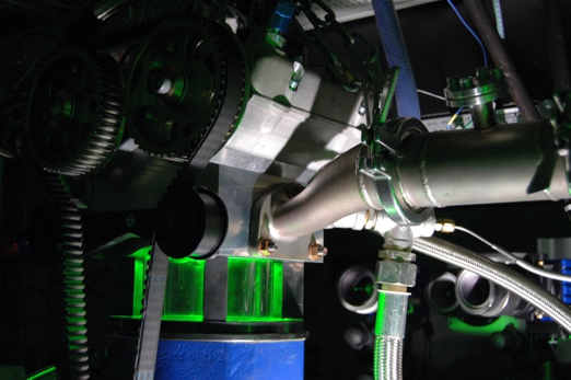
|align="left"|'''Figure 1:''' Photograph of the optically accessible engine. The in-cylinder volume is illuminated by the green laser-sheet used for the flow field measurements using particle image velocimetry (PIV). | |||
|} | |||
<br/> | <br/> | ||
---- | ---- | ||
{{ACContribs | {{ACContribs | ||
|authors=Carl Philip Ding | |authors=Carl Philip Ding, Rene Honza, Elias Baum, Benjamin Böhm, Andreas Dreizler | ||
|organisation=Technische Universität Darmstadt | |organisation=Fachgebiet Reaktive Strömungen und Messtechnik (RSM),Technische Universität Darmstadt, Germany | ||
}} | |||
{{ACContribs | |||
|authors=Brian Peterson | |||
|organisation=School of Engineering, University of Edinburgh, Scotland UK | |||
}} | |||
{{ACContribs | |||
|authors=Chao He, Wibke Leudesdorff, Guido Kuenne, Amsini Sadiki, Johannes Janicka | |||
|organisation=Fachgebiet Energie und Kraftwerkstechnik (EKT), Technische Universität Darmstadt, Germany | |||
}} | |||
{{ACContribs | |||
|authors=Peter Janas, Andreas Kempf | |||
|organisation=Institut für Verbrennung und Gasdynamik (IVG), Lehrstuhl für Fluiddynamik, Universität Duisburg-Essen, Germany | |||
}} | |||
{{ACContribs | |||
|authors=Stefan Buhl, Christian Hasse | |||
|organisation=Fachgebiet Simulation reaktiver Thermo-Fluid Systeme (STFS), Technische Universität Darmstadt, Germany; former: Professur Numerische Thermofluiddynamik (NTFD), Technische Universität Bergakademie Freiberg, Germany | |||
}} | }} | ||
{{ACHeader | {{ACHeader | ||
| Line 70: | Line 47: | ||
© copyright ERCOFTAC 2018 | © copyright ERCOFTAC 2018 | ||
Latest revision as of 11:36, 14 January 2022
Internal combustion engine flows for motored operation
Application Area 2: Combustion
Application Challenge AC2-10
Abstract
This test case provides data on the in-cylinder flow for an IC engine under motored operation. The Technische Universität Darmstadt engine features a typical design of a modern spark-ignition direct injection engine. It is an optically accessible single cylinder engine especially designed to provide well characterized boundary conditions and reproducible engine operation, a prerequisite for any comparison of experiments and simulations. The in-cylinder flow is characterized by various particle image velocimetry (PIV) techniques to provide measurements at high spatial and temporal resolution. The database for validation includes the first two statistical moments (mean and rms) of velocities, spatial flow structures and the temporal evolution of the flow field over the entire engine cycle in the central tumble plane. Information on the 3D flow is available within a volume up to 8 mm thick centered on the central tumble plane. Important boundary conditions such as the in-cylinder, intake- and exhaust-port pressures as well as temperatures are given. Simulation results obtained from three investigations using LES (Large Eddy Simulation) and hybrid URANS (unsteady Reynolds-averaged Navier-Stokes)/LES are presented and compared with the experimental results.

|
| Figure 1: Photograph of the optically accessible engine. The in-cylinder volume is illuminated by the green laser-sheet used for the flow field measurements using particle image velocimetry (PIV). |
Contributed by: Carl Philip Ding, Rene Honza, Elias Baum, Benjamin Böhm, Andreas Dreizler — Fachgebiet Reaktive Strömungen und Messtechnik (RSM),Technische Universität Darmstadt, Germany
Contributed by: Brian Peterson — School of Engineering, University of Edinburgh, Scotland UK
Contributed by: Chao He, Wibke Leudesdorff, Guido Kuenne, Amsini Sadiki, Johannes Janicka — Fachgebiet Energie und Kraftwerkstechnik (EKT), Technische Universität Darmstadt, Germany
Contributed by: Peter Janas, Andreas Kempf — Institut für Verbrennung und Gasdynamik (IVG), Lehrstuhl für Fluiddynamik, Universität Duisburg-Essen, Germany
Contributed by: Stefan Buhl, Christian Hasse — Fachgebiet Simulation reaktiver Thermo-Fluid Systeme (STFS), Technische Universität Darmstadt, Germany; former: Professur Numerische Thermofluiddynamik (NTFD), Technische Universität Bergakademie Freiberg, Germany
© copyright ERCOFTAC 2018
