Best Practice Advice AC1-01: Difference between revisions
No edit summary |
No edit summary |
||
| Line 17: | Line 17: | ||
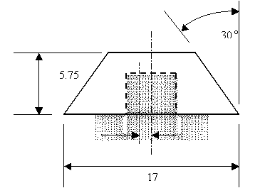
[[Image:d34_image004.gif]] (Figure dimensions in inches) | [[Image:d34_image004.gif]] (Figure dimensions in inches) | ||
M219 Transonic Cavity | M219 Transonic Cavity | ||
M∞ = 0.85 | M∞ = 0.85 | ||
Revision as of 15:30, 1 September 2008
Aero-acoustic cavity
Application Challenge 1-01 © copyright ERCOFTAC 2004
Best Practice Advice for the AC
Key Fluid Physics
Description of Application Challenge
                               M219 Transonic Cavity
                               M∞ = 0.85
                               L/D (length/depth ratio) = 5
• W/D (width/depth ratio) = 1
• ReL = 6.84x10⁶
DOAPs
On 10 points along cavity ceiling;
• RMS pressures
• Power Spectral Density (PSD) or Sound Pressure Level (SPL)
Flow Physics
• Sharp edge separation
• Cavity flow recirculation
• Shear layer oscillation. The DOAPs are driven by the shear layer oscillation, therefore it is important to resolve this feature well.
• Large eddy structures
• Coherent (vortex shedding) and broadband (turbulent) structures
Underlying Flow Regimes
• Cavity Flow
• 2D Unsteady Shear Layer
Neither of these are in the Knowledge Base. © ERCOFTAC 2004 Application Uncertainties
• Upstream turbulence level
• Boundary layer ahead of cavity leading edge – not known whether the boundary layer is tripped or not. © ERCOFTAC 2004 Computational Domain and Boundary Conditions
Computational Domain
• Upstream domain starts at rig sharp leading edge, downstream one cavity length behind cavity trailing edge.
• Side domains one cavity width away from side edge.
Boundary Conditions
• M=0.85, T=305.06K on upstream boundary
• Side boundaries, top boundary and downstream boundary, constant pressure = 62059.14Pa
• No slip conditions on cavity walls, with hybrid low-Re / wall-function © ERCOFTAC 2004 Discretisation and Grid Resolution
• Second-order special discretisation (MARS) on momentum
• Hexahedral orthogonal meshes with successive 2x2 refinement into the shear layer and walls are necessary. Mesh dependency analysis shows low sensitivity to refiments greater than 40000 cells in the 2D plane.
• Better than 1st order temporal discretsation © ERCOFTAC 2004 Physical Modelling
• Transient
• Compressible ideal gas
• Low-Reynolds number k-epsilon (linear and non-liners) turbulence models © ERCOFTAC 2004 Recommendations for Future Work
• Extension to 3D
• LES-based turbulence modeling
• Full second-order central differencing special discretisation in the LES flow regions
Both these recommendations have been followed in later studies reported by the Application Challenge Author – see additional reference section below [1,3]. © ERCOFTAC 2004 Additional References
[1] Mendonca, F., Allen, R., de Charentenay, J. and Kirkham, D., “CFD Prediction of narrowband and broadband cavity acoustics at M=0.85”, AIAA-2003-3303, 9th AIAA/CEAS Aeroacoustics Conference and Exhibit, Hilton Head, South Carolina, USA, May 2003.
[2] Allen, R., and Mendonça, F., “DES Predictions on the M219 cavity at M=0.85”, Colloquium EUROMECH 449, Chamonix, France, 7-8th December 2003
[3] Allen, R., and Mendonça, F., “DES Validations of Cavity Acoustics over the subsonic to Supersonic Range”, AIAA-2004-2862, 10th AIAA/CEAS Aeroacoustics Conference and Exhibit, Manchester, UK, May 2004 © copyright ERCOFTAC 2004
Contributors: Fred Mendonca; Richard Allen - Computational Dynamics Ltd
Site Design and Implementation: Atkins and UniS
Top Next

