UFR 2-04 References: Difference between revisions
David.Fowler (talk | contribs) (New page: {{UFR|front=UFR 2-04|description=UFR 2-04 Description|references=UFR 2-04 References|testcase=UFR 2-04 Test Case|evaluation=UFR 2-04 Evaluation|qualityreview=UFR 2-04 Quality Review|bestp...) |
David.Fowler (talk | contribs) |
||
| Line 15: | Line 15: | ||
== References == | == References == | ||
Biswas D., and Fukuyama, Y., (1994), Calculation of Transitional Boundary Layers with an Improved Low-Reynolds-Number Version of k | Biswas D., and Fukuyama, Y., (1994), Calculation of Transitional Boundary Layers with an Improved Low-Reynolds-Number Version of k-[[Image:U2-04d32_files_image027.gif]] Turbulence Model,''' ASME J. Turbomachinery''', Vol. 116, pp. 765-773. | ||
Biswas D., Iwasaki, H., and Ishizuka, M., (1997), Numerical Analysis of Two-Dimensional Compressible Viscous Flow in Turbomachinery Cascades Using an Improved | Biswas D., Iwasaki, H., and Ishizuka, M., (1997), Numerical Analysis of Two-Dimensional Compressible Viscous Flow in Turbomachinery Cascades Using an Improved k-[[Image:U2-04d32_files_image028.gif]] | ||
Craft, T. J., Launder, B. E., and Suga, K., (1993), Extending the Applicability of Eddy viscosity Models through the Use of Deformation Invariants and Non-Linear Elements, '''''Proc. 5<sup>th</sup> Int. Symp. Refined Flow Modelling and Turbulent Measurements''''', p. 125. | Craft, T. J., Launder, B. E., and Suga, K., (1993), Extending the Applicability of Eddy viscosity Models through the Use of Deformation Invariants and Non-Linear Elements, '''''Proc. 5<sup>th</sup> Int. Symp. Refined Flow Modelling and Turbulent Measurements''''', p. 125. | ||
| Line 43: | Line 43: | ||
Mayle, R. E., (1991), The Role of Laminar-Turbulent Transition in Gas Turbine Engines, '''ASME J. Turbomachinery''', Vol. 113, pp. 509537. | Mayle, R. E., (1991), The Role of Laminar-Turbulent Transition in Gas Turbine Engines, '''ASME J. Turbomachinery''', Vol. 113, pp. 509537. | ||
Menter, F. R., (1992), Improved Two-Equation k | Menter, F. R., (1992), Improved Two-Equation k-[[Image:U2-04d32_files_image029.gif]]NASA TM 103975. | ||
Schmidt, R. C., and Patankar, S. V., (1991), Simulating Boundary Layer Transition with Low-Reynolds-Number k | Schmidt, R. C., and Patankar, S. V., (1991), Simulating Boundary Layer Transition with Low-Reynolds-Number k-[[Image:U2-04d32_files_image030.gif]] Turbulence Models. I - An Evaluation of Prediction Characteristics. II - An Approach to Improving the Predictions, '''ASME J. Turbomachinery''', Vol. 113, pp. 10-26. | ||
Shreeve, R. P., Elazar, Y., Dreon, J. W., and Baydar, A., (1991), Wake Measurements and Loss Evaluation in a Controlled Diffusion Cascade, '''ASME J. Turbomachinery''', Vol. 113, pp. 591-599. | Shreeve, R. P., Elazar, Y., Dreon, J. W., and Baydar, A., (1991), Wake Measurements and Loss Evaluation in a Controlled Diffusion Cascade, '''ASME J. Turbomachinery''', Vol. 113, pp. 591-599. | ||
| Line 82: | Line 82: | ||
|- | |- | ||
| style="width: 253.2pt; padding: 0cm 5.4pt 0cm 5.4pt" width="338" valign="top" | | | style="width: 253.2pt; padding: 0cm 5.4pt 0cm 5.4pt" width="338" valign="top" | | ||
'''Figure | '''Figure 2'''<nowiki>: Schematic of the cascade wind tunnel (from Elazar and Shreeve, 1990).</nowiki> | ||
| style="width: 253.2pt; padding: 0cm 5.4pt 0cm 5.4pt" width="338" valign="top" | | | style="width: 253.2pt; padding: 0cm 5.4pt 0cm 5.4pt" width="338" valign="top" | | ||
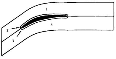
'''Figure | '''Figure 3'''<nowiki>: Cascade passage geometry and LDV measuring stations (from Elazar and Shreeve, 1990).</nowiki> | ||
|} | |} | ||
| Line 108: | Line 108: | ||
''' ''' | ''' ''' | ||
'''Figure | '''Figure 4'''<nowiki>: Alternative grid arrangements used by Lien et al. (1996).</nowiki><br /> Upper: H-type grid (in either single block or multi-block arrangements).<br /> Middle: H-/O-type multi-block grid arrangement.<br /> Lower: Details of the two grids in the leading edge region. | ||
|} | |} | ||
| Line 131: | Line 131: | ||
|- | |- | ||
| style="width: 506.4pt; padding: 0cm 5.4pt 0cm 5.4pt" colspan="2" width="675" valign="top" | | | style="width: 506.4pt; padding: 0cm 5.4pt 0cm 5.4pt" colspan="2" width="675" valign="top" | | ||
'''Figure | '''Figure 5'''<nowiki>: Pressure coefficient distributions along the blade chord. Clock-wise from upper right: Lien et al. (1996), Tselepidakis (1996), Biswas et al. (1997) and Kang et al. (1995).</nowiki> | ||
|} | |} | ||
| Line 147: | Line 147: | ||
|- | |- | ||
| style="width: 506.4pt; padding: 0cm 5.4pt 0cm 5.4pt" colspan="2" width="675" valign="top" | | | style="width: 506.4pt; padding: 0cm 5.4pt 0cm 5.4pt" colspan="2" width="675" valign="top" | | ||
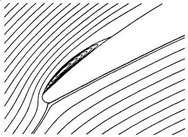
'''Figure | '''Figure 6'''<nowiki>: Stream function contours at the leading edge. Right: Tselepidakis (1996), left: Kang et al. (1995).</nowiki> | ||
|} | |} | ||
| Line 159: | Line 159: | ||
|- | |- | ||
| style="width: 506.4pt; padding: 0cm 5.4pt 0cm 5.4pt" colspan="2" width="675" valign="top" | | | style="width: 506.4pt; padding: 0cm 5.4pt 0cm 5.4pt" colspan="2" width="675" valign="top" | | ||
'''Figure | '''Figure 7'''<nowiki>: Pressure loss coefficient (left) and exit flow angle (right) distributions (from Kang et al., 1995).</nowiki> | ||
|} | |} | ||
| Line 169: | Line 169: | ||
|- | |- | ||
| style="width: 506.4pt; padding: 0cm 5.4pt 0cm 5.4pt" width="675" valign="top" | | | style="width: 506.4pt; padding: 0cm 5.4pt 0cm 5.4pt" width="675" valign="top" | | ||
'''Figure | '''Figure 8'''<nowiki>: Boundary layer parameters distributions. Left: Boundary layer thickness. Middle: Displacement thickness. Right: Momentum thickness (from Lien et al., 1996).</nowiki> | ||
|} | |} | ||
| Line 183: | Line 183: | ||
|- | |- | ||
| style="width: 506.4pt; padding: 0cm 5.4pt 0cm 5.4pt" colspan="3" width="675" valign="top" | | | style="width: 506.4pt; padding: 0cm 5.4pt 0cm 5.4pt" colspan="3" width="675" valign="top" | | ||
'''Figure | '''Figure 9'''<nowiki>: Left: Boundary layer shape factor. Middle: Downstream wake velocity distribution. Right: Variation of minimum velocity with distance (from Biswas et al., 1997).</nowiki> | ||
|} | |} | ||
| Line 205: | Line 205: | ||
|- | |- | ||
| style="width: 511.35pt; padding: 0cm 5.4pt 0cm 5.4pt" colspan="2" width="682" valign="top" | | | style="width: 511.35pt; padding: 0cm 5.4pt 0cm 5.4pt" colspan="2" width="682" valign="top" | | ||
'''Figure | '''Figure 10'''<nowiki>: Stream velocity (left) and turbulence intensity (right) profiles on suction side (from Tselepidakis, 1996).</nowiki> | ||
|} | |} | ||
Revision as of 17:22, 3 March 2009
Flow around (airfoils and) blades (subsonic)
Underlying Flow Regime 2-04 © copyright ERCOFTAC 2004
References
Biswas D., and Fukuyama, Y., (1994), Calculation of Transitional Boundary Layers with an Improved Low-Reynolds-Number Version of k-![]() Turbulence Model, ASME J. Turbomachinery, Vol. 116, pp. 765-773.
Turbulence Model, ASME J. Turbomachinery, Vol. 116, pp. 765-773.
Biswas D., Iwasaki, H., and Ishizuka, M., (1997), Numerical Analysis of Two-Dimensional Compressible Viscous Flow in Turbomachinery Cascades Using an Improved k-![]()
Craft, T. J., Launder, B. E., and Suga, K., (1993), Extending the Applicability of Eddy viscosity Models through the Use of Deformation Invariants and Non-Linear Elements, Proc. 5th Int. Symp. Refined Flow Modelling and Turbulent Measurements, p. 125.
Deutsch, S., and Zierke, W. C., (1987), The Measurement of Boundary Layers on a Compressor Blade in Cascade: Part 1 - A Unique Experimental Facility, ASME Paper 87-GT-248.
Deutsch, S., and Zierke, W. C., (1987), The Measurement of Boundary Layers on a Compressor Blade in Cascade: Part 2 - Suction Surface Boundary Layers, ASME Paper 87-GT-249.
Deutsch, S., and Zierke, W. C., (1987), The Measurement of Boundary Layers on a Compressor Blade in Cascade: Part 3 - Pressure Surface Boundary Layers and the Near Wake, ASME Paper 87-GT-250.
Elazar, Y., and Shreeve, R. P., (1990), Viscous Flow in a Controlled Diffusion Compressor Cascade With Increasing Incidence, ASME J. Turbomachinery, Vol. 112, pp. 256-266.
Emmons, H. W., (1951), The Laminar-Turbulent Transition in a Boundary Layer Part I, J. Aerospace Science, Vol. 18, No. 7, pp. 490-498.
Kang, S.-H., Lik, J. S., Choi M.-R., and Kim, K.-Y., (1995), Numerical Calculations of the Turbulent Flow Through a Controlled Diffusion Compressor Cascade, ASME J. Turbomachinery, Vol. 117, pp. 223-230.
Launder, B. E., and Sharma, B. I., (1974), Application of the Energy-Dissipation Model of Turbulence to the Calculation of Flows Near a Spinning Disk, Letters Heat Mass Transfer, Vol. 1, pp. 131-138.
Leonard, B. P., (1979), A Stable and Accurate Convective Modelling Procedure Based on Quadratic Upstream Interpolation, Comp. Meth. Applied Mech. Engineering, Vol. 19, pp. 59-98.
Lien, F. S., Chen, W. L., and Leschziner, M. A., (1996), A Multiblock Implementation of a Non-Orthogonal, Collocated Finite Volume Algorithm for Complex Turbulent Flows, Int. J. Num. Methods Fluids, Vol. 23, pp. 567-588.
Lien, F. S., and Leschziner, M. A., (1993), Computational Modelling of 3D Turbulent flow in S-Diffuser and Transition Ducts, Letters Heat Mass Transfer, Vol. 131.
Mayle, R. E., (1991), The Role of Laminar-Turbulent Transition in Gas Turbine Engines, ASME J. Turbomachinery, Vol. 113, pp. 509537.
Menter, F. R., (1992), Improved Two-Equation k-![]() NASA TM 103975.
NASA TM 103975.
Schmidt, R. C., and Patankar, S. V., (1991), Simulating Boundary Layer Transition with Low-Reynolds-Number k-![]() Turbulence Models. I - An Evaluation of Prediction Characteristics. II - An Approach to Improving the Predictions, ASME J. Turbomachinery, Vol. 113, pp. 10-26.
Turbulence Models. I - An Evaluation of Prediction Characteristics. II - An Approach to Improving the Predictions, ASME J. Turbomachinery, Vol. 113, pp. 10-26.
Shreeve, R. P., Elazar, Y., Dreon, J. W., and Baydar, A., (1991), Wake Measurements and Loss Evaluation in a Controlled Diffusion Cascade, ASME J. Turbomachinery, Vol. 113, pp. 591-599.
Steelant, J., and Dick, E., (1996), Modelling of Bypass Transition with Conditioned Navier-Stokes Equations Coupled to an Intermittency Transport Equation, Int. J. Num. Methods Fluids, Vol. 23, pp. 193220.
Suzen, Y. B., and Huang, P. G., (2000), Modelling of Flow Transition Using an Intermittency Transport Equation, ASME J. Fluids Engineering, Vol. 122, pp.273-284.
Tselepidakis, D. P., (1996), Modelling and Prediction of the Laminar Leading-Edge Separation and Transition in a Blade-Cascade Flow, ASME Paper 96-GT-411.
Zierke, W. C., and Deutsch, S., (1989), The Measurement of Boundary Layers on a Compressor Blade in Cascade: Part 4 - Flow Fields for Incidence Angles of -1.5 and -8.5 Degrees, ASME Paper 89-GT-71, also ASME J. Turbomachinery, Vol. 112, pp. 241-255 (1990).
Wilcox, D. C., (1994), Simulation of Transition with a Two-Equation Turbulence Model, AIAA J., Vol. 32, p. 247.
 |
|
|
 |
 |
|
Figure 2: Schematic of the cascade wind tunnel (from Elazar and Shreeve, 1990). |
Figure 3: Cascade passage geometry and LDV measuring stations (from Elazar and Shreeve, 1990). |
 |
 |
 |
 |
|
Figure 5: Pressure coefficient distributions along the blade chord. Clock-wise from upper right: Lien et al. (1996), Tselepidakis (1996), Biswas et al. (1997) and Kang et al. (1995). | |
 |
 |
|
Figure 6: Stream function contours at the leading edge. Right: Tselepidakis (1996), left: Kang et al. (1995). | |
 |
 |
|
Figure 7: Pressure loss coefficient (left) and exit flow angle (right) distributions (from Kang et al., 1995). | |
 |
|
Figure 8: Boundary layer parameters distributions. Left: Boundary layer thickness. Middle: Displacement thickness. Right: Momentum thickness (from Lien et al., 1996). |
 |
 |
 |
|
Figure 9: Left: Boundary layer shape factor. Middle: Downstream wake velocity distribution. Right: Variation of minimum velocity with distance (from Biswas et al., 1997). | ||
 |
 |
 |
 |
|
Figure 10: Stream velocity (left) and turbulence intensity (right) profiles on suction side (from Tselepidakis, 1996). | |
© copyright ERCOFTAC 2004
|
Contributors: E. S. Politis - NTUA
|


