Abstr:Curved passage flow
Confined Flows
Underlying Flow Regime 4-05
Abstract
Three main flow patterns are potential sources of losses in turbomachinery. These are:
- The passage vortex, which is generated by the interaction of the pressure gradient and the boundary layers near the solid walls.
- The horseshoe vortex, which is generated by the interaction of the boundary layers on the end walls with a leading edge when the flow is curved by blades. This vortex starts at the leading edge near the end walls and develops in the inter-blade passage.
- The wake, which is the lower velocity flow generated behind a blade.
The two kinds of vortex and the wake often interact to form loss cores inside the flow behind the blade passage. The correct simulation of the losses is of course of great importance for who wants to predict the efficiency of his machine. Thus, the CFD simulations of such flows must capture the different vortex structure with high precision.
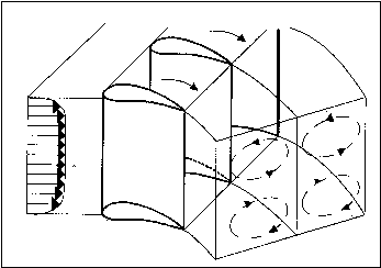
The physics of the underlying flow regime of a curved passage flow is governed by the interaction of the pressure gradient linked to the curvature of the main flow with the non-uniform flow (for instance due to boundary layers on solid walls). The flow, moving slower in the boundary layers, is pushed from the pressure side to the suction side, leading to an overturning in the end-wall regions. This gives rise to stream-wise vorticity generating an end-wall vortex in the curved passage (as illustrated on Figure 1:). It should be pointed out that the basic mechanics of this secondary flow generation is inviscid. Furthermore, due to the presence of a rounded leading edge, horseshoe vortices are also generated, which merge with the passage vortices.
The correct representation of this flow regime is of importance because:
- It induces extra losses.
- It leads to significant tri-dimensional flow effects with 3D separation on the blade suction side.
- It induces a non-uniform heat transfer on the blade and end-wall surfaces and has a strong influence on the blade film cooling.
- It affects the blade lifetime because of enhanced thermal and mechanical stresses.
- It has an influence on the turbine stage work output.
- It has an impact on downstream blade row efficiency due to an enhanced non-uniformity of the exit flow.
This flow regime is influenced by numerous factors such as the blade shape, the pitch-chord ratio, the aspect ratio, the Mach number, and the inlet boundary layer thickness. Owing to its importance in turbomachinery design and to its interaction with other secondary motions, an excessive amount of work has been done on this flow regime. Therefore, a full and concise review of the literature on this UFR is far from trivial and will not be conducted here.
Since this underlying flow regime focuses on accelerating passage flow, the related secondary flows will be weak compared to decelerating flow. Furthermore, this study will mainly focus on the influence of the mesh and the turbulence model onto the underlying flow regime.
Contributors: Nouredine Hakimi - NUMECA International

