UFR 4-03 Test Case
Pipe flow - rotating
Underlying Flow Regime 4-03 © copyright ERCOFTAC 2004
Test Case
Brief description of the study test case
In the three-dimensional case, expressing the Navier-Stokes equations in primitive variables reduces the number of operations necessary to integrate the equations numerically. In cylindrical coordinates, when the variables ![]() are introduced, the continuity equations becomes:
are introduced, the continuity equations becomes:
It is clear that the quantities ![]() do not all have the same physical dimensions; this could be a matter of confusion. We wish to point out that these variables have been introduced for numerical reasons only. As discussed later, the introduction of
do not all have the same physical dimensions; this could be a matter of confusion. We wish to point out that these variables have been introduced for numerical reasons only. As discussed later, the introduction of ![]() simplifies the treatment of the singularity at r=0 and
simplifies the treatment of the singularity at r=0 and ![]() permits better accuracy near the axis. The Navier-Stokes equations in terms of the new variables, in a reference frame rotating with the pipe wall, are:
permits better accuracy near the axis. The Navier-Stokes equations in terms of the new variables, in a reference frame rotating with the pipe wall, are:


The equations nondimensionalized by the centreline stream-wise velocity ![]() of the laminar Poiseuille flow and by the pipe radius R give the dimensionless numbers
of the laminar Poiseuille flow and by the pipe radius R give the dimensionless numbers ![]() and
and ![]() . In this paper rather than the Rossby number
. In this paper rather than the Rossby number ![]() usually used in geophysical problems, the rotation number
usually used in geophysical problems, the rotation number ![]() has been adopted. This choice has been dictated by the fact that N was previously used in studies of turbulent flows in rotating pipes. The mean pressure gradient in the streamwise direction maintains the bulk velocity
has been adopted. This choice has been dictated by the fact that N was previously used in studies of turbulent flows in rotating pipes. The mean pressure gradient in the streamwise direction maintains the bulk velocity ![]() constant; it is evaluated by integrating the discretized
constant; it is evaluated by integrating the discretized ![]() equation in the whole domain.
equation in the whole domain. ![]() is related to the mean wall friction velocity
is related to the mean wall friction velocity ![]() by
by ![]() .
.

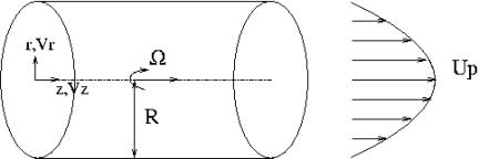
Figure 1 Flow Configuration.
The flow configuration is shown in Figure 1.
Test Case Experiments
Durst Jovanovic & Sender (1995) carried out LDA measurements in the near wall region of a turbulent pipe flow. This test experiment has been chosen to validate the CFD at N=0 (no-rotation). The experimental facility consist of a closed--loop pipe flow installation driven by a screw conveyor pump operating in suction mode. This screw conveyor pump was chosen because of its very low flow-rate pulsations. Electronic control of the pump was available which allowed flow--rate setting with a tolerance of 1%. Reynolds number ranged from 7442 to 30.000. In order to permit laser-Doppler measurements, the test section was made from a Duran-50 glass pipe. To avoid interference of the pipe with the light beams, the test fluid was a two mixed DIESEL oil in order to be refractive-index-matched to the Duran glass. Heating and cooling system controlled the flow temperature. The laser--Doppler is composed of a 30 mW helium neon laser and double Brag cell transmission optics.
For low rotation rates the experiment by Kikuyama et al. (1983) was considered. The velocity profile at the inlet section was made uniform and with low turbulence levels (.3%) with a honeycomb and 6 screens and a nozzle with aspect ratio 12.3:1. A step ring of 1mm height was installed at the exit section of the nozzle to ensure to flow be turbulent in the boundary layer. Hot wires probes were used to measure velocities at x/D=2.7,5.7,9.7,15.5,22.5 (x is the distance from the inlet section) for ![]() . The probes were inserted through a small hole drilled in a narrow stationary ring 10mm in length placed between two rotating sections.
. The probes were inserted through a small hole drilled in a narrow stationary ring 10mm in length placed between two rotating sections.
For higher rotation rates CFD results have been compared with the experiments carried out by Reich & Beer (1989). In the experiment by Reich & Beer (1989), in order to obtain fully developed flow conditions, the air was passed through an air filter into the inlet section, which is a non--rotating pipe with a diameter of D=50mm and a dimensionless length of L/D=50. The length of the ensuing rotating test section could be varied in the range 0<L/D<120. At the end of the rotating pipe a narrow non rotating ring of 3mm length was inserted for measurements.
A cylindrical three-hole aerodynamic probe was inserted into the rotating ring and transversed in the radial direction, in order to obtain axial and tangential velocity profiles. Behind the non--rotating ring a second rotating pipe section (L/D=10), a mixing chamber for measuring of temperature, a downstream non-rotating pipe, a Venturi nozzle for measuring the flow rate and a centrifugal blower were arranged. The rotating tube wall temperature was measured with chromel-alumel thermocouples. To prevent vibration due to rotation, the pipe was supported by a series of ball bearings located at intervals of L/D=20. The flow-rate Reynolds number was varied in the range ![]() and the rotational Reynolds number in the range
and the rotational Reynolds number in the range ![]()
CFD Methods
Orlandi & Fatica (1997) have performed DNS of the turbulent rotating pipe flow. The numerical scheme described in detail in the paper by Verzicco and Orlandi (1996) is here recalled briefly. The system of equations was solved by a fractional step method (Rai and Moin 1991). In a first step a non-solenoidal velocity field ![]() . A scalar quantity Φ is introduced to project the non-solenoidal field onto a solenoidal one. The large band matrix associated to the elliptic equation for Φ is reduced to a tridiagonal matrix by periodic FFTs in the azimuthal and in the axial directions. The updated pressure is computed from the scalar Φ. A third order Runge-Kutta scheme, described by Rai and Moin (1991), was used to advance in time, through three sub-steps. The viscous terms are treated implicitly by the Crank-Nicolson scheme.
. A scalar quantity Φ is introduced to project the non-solenoidal field onto a solenoidal one. The large band matrix associated to the elliptic equation for Φ is reduced to a tridiagonal matrix by periodic FFTs in the azimuthal and in the axial directions. The updated pressure is computed from the scalar Φ. A third order Runge-Kutta scheme, described by Rai and Moin (1991), was used to advance in time, through three sub-steps. The viscous terms are treated implicitly by the Crank-Nicolson scheme.

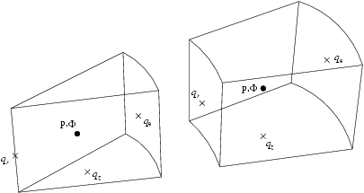
In cylindrical coordinates, as mentioned before, the equations for the velocity components are singular at r=0. If staggered "fluxes" are used (see Figure 2), one can set ![]() at the centreline, and the
at the centreline, and the ![]() equation can be discretized at the points (
equation can be discretized at the points (![]() ) without any approximation. The viscous terms in the radial direction at the first point close to the wall, for the
) without any approximation. The viscous terms in the radial direction at the first point close to the wall, for the ![]() and
and ![]() equations have been approximated as done by Rai and Moin (1991) for the plane channel. The discretization of the
equations have been approximated as done by Rai and Moin (1991) for the plane channel. The discretization of the ![]() and
and ![]() equations at the first grid position near the axis does not require any approximation for the radial derivatives. Periodicity has been imposed in the stream-wise direction in a domain of different length
equations at the first grid position near the axis does not require any approximation for the radial derivatives. Periodicity has been imposed in the stream-wise direction in a domain of different length ![]() depending on the rotation number N.
depending on the rotation number N.
Finite differences have the advantages to use arbitrary coordinates transformation to cluster grid points in regions of high gradients. An analytical transformation by the hyperbolic tangent allowed to have the first grid point at a distance ![]() from the wall. This clustering is necessary to fully resolve the thin vortical layers near the wall responsible for the wall friction and for the turbulence production. Although the Reynolds numbers is low the grid spacing in the central region of the pipe is not small enough to consider the flow fully resolved. However the grid spacing was close to those used in the full channel by KMM. Moreover it is clear that the resolution for the circular pipe is better than in the plane channel, since the polar coordinates reduce the size
from the wall. This clustering is necessary to fully resolve the thin vortical layers near the wall responsible for the wall friction and for the turbulence production. Although the Reynolds numbers is low the grid spacing in the central region of the pipe is not small enough to consider the flow fully resolved. However the grid spacing was close to those used in the full channel by KMM. Moreover it is clear that the resolution for the circular pipe is better than in the plane channel, since the polar coordinates reduce the size ![]() of the physical grid moving towards the axis. In the three-dimensional case, in the limit of
of the physical grid moving towards the axis. In the three-dimensional case, in the limit of ![]() energy is conserved by the discretized equations. The check of the accurate treatment of the singularity was done by letting a dipole to move across the axis where large variations of radial velocity occur. The simulation showed that the dipolar structure maintains its shape and that in the inviscid case the energy was conserved.
energy is conserved by the discretized equations. The check of the accurate treatment of the singularity was done by letting a dipole to move across the axis where large variations of radial velocity occur. The simulation showed that the dipolar structure maintains its shape and that in the inviscid case the energy was conserved.
Feiz, Oul-Rouis & Lauriat (2003) performed the Large Eddy Simulation with two subgrid models, a dynamic model and the usual Smagorinsky model. In the Smagorinsky model, the subgrid scale eddy viscosity is related to the deformation of the resolved velocity field as:
![]() where
where ![]() . This subgrid model, largely used in LES of isotropic turbulence produced good results. When it was applied to inhomogeneous and in particular to wall bounded flows the constant was modified. The dynamic model provides a methodology for determining an appropriate local value of the Smagorinsky coefficient. The model was proposed by Germano et al. (1991) and later improved by Lilly (1992). The turbulent viscosity is expressed using an eddy viscosity assumption as
. This subgrid model, largely used in LES of isotropic turbulence produced good results. When it was applied to inhomogeneous and in particular to wall bounded flows the constant was modified. The dynamic model provides a methodology for determining an appropriate local value of the Smagorinsky coefficient. The model was proposed by Germano et al. (1991) and later improved by Lilly (1992). The turbulent viscosity is expressed using an eddy viscosity assumption as ![]() with the value of the constant
with the value of the constant ![]() computed during the simulation from the flow variables.
computed during the simulation from the flow variables.
 , where
 ![]() ,
, ![]() . The constant could be positive or negative. The positive values are linked to energy flowing from large to small scales, and the negative to energy going from small to large scales (backward energy transfer). A grid (65, 39, 65), non uniform in the radial direction and uniform in the other two directions was used. The pipe length was
. The constant could be positive or negative. The positive values are linked to energy flowing from large to small scales, and the negative to energy going from small to large scales (backward energy transfer). A grid (65, 39, 65), non uniform in the radial direction and uniform in the other two directions was used. The pipe length was ![]() the Reynolds number
the Reynolds number ![]() and two different rotation rates
and two different rotation rates ![]() and
and ![]()
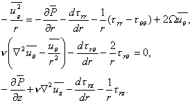
The Reynolds averaged form of the Navier-Stokes equations, under fully developed conditions (![]() and
and ![]() take the form:
take the form:

A non-zero mean swirl velocity is generated by the shear component ![]() of the Reynolds stress tensor. In order to guarantee that this component is non-zero and that the flow is not unidirectional, as indicated by experiments, non-zero
of the Reynolds stress tensor. In order to guarantee that this component is non-zero and that the flow is not unidirectional, as indicated by experiments, non-zero ![]() Reynolds shear stress must be generated by the axial mean velocity
Reynolds shear stress must be generated by the axial mean velocity ![]() et al. (2000) discussed the capability of several closure models to predict a swirl velocity and an axial velocity depending on
et al. (2000) discussed the capability of several closure models to predict a swirl velocity and an axial velocity depending on ![]() . Here, the main conclusions are summarised, details are in the paper.
. Here, the main conclusions are summarised, details are in the paper.
The standard and nonlinear ![]() models, like all traditional two equation models with conventional near-wall treatments, are incapable of predicting the main physical features of turbulent flow in an axially rotating pipe.
models, like all traditional two equation models with conventional near-wall treatments, are incapable of predicting the main physical features of turbulent flow in an axially rotating pipe.
Since the two-dimensional explicit algebraic stress model does not generate a non-zero Reynolds shear stress ![]() , there will be no mean swirl velocity. However, unlike the standard and nonlinear
, there will be no mean swirl velocity. However, unlike the standard and nonlinear ![]() models, it does predict a rotationally dependent axial mean velocity, which is the more significant effect.
models, it does predict a rotationally dependent axial mean velocity, which is the more significant effect.
The three-dimensional form of the explicit algebraic stress models is much more complicated. A mean swirl velocity arises from a cubic nonlinearity in conventional explicit algebraic stress models.
A non-zero mean swirl velocity will be predicted in axially rotating pipe flow by virtually all existing second order closures by the presence of Coriolis terms.
© copyright ERCOFTAC 2004
Contributors: Stefano Leonardi - Universita di Roma 'La Sapienza'