Test Data AC2-08
Premixed Methane-Air Swirl Burner (TECFLAM)
Application Challenge 2-08 © copyright ERCOFTAC 2011
Overview and Boundary Data
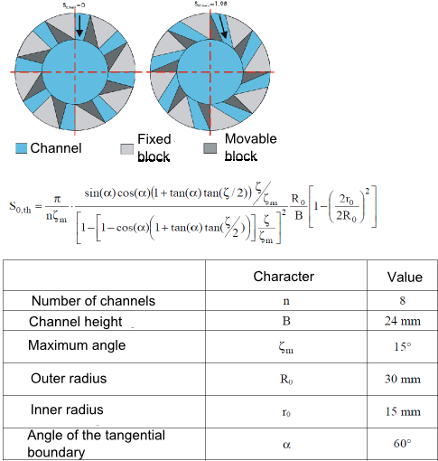
The same geometry of the swirl nozzle represented by the theoretical swirl number (S0,th) is used for all testcases considered here. It is defined by the angle of the movable block as illustrated in Fig. 3.1.
The boundary and operating conditions of the four cases are summarized in table 3.1.
|
|
|
|
|
|
| 30iso | 150iso | PSF-30 | PSF-150 | |
|
|
|
|
|
|
| S0,th ( - ) | 0.75 | 0.75 | 0.75 | 0.75 |
| P ( kW ) | - | - | 30 | 150 |
| ϕ ( - ) | - | - | 0.833 | 1.0 |
| Qgas(mn3∕h) | 0 | 0 | 3.02 | 15.11 |
| Qair(mn3∕h) | 35.6 | 149.6 | 34.91 | 145.4 |
| ubulk ( m/s ) | 4.66 | 19.57 | 4.95 | 21.03 |
| Re ( - ) | 9,680 | 40,690 | 9,970 | 42,300 |
|
|
|
|
|
|
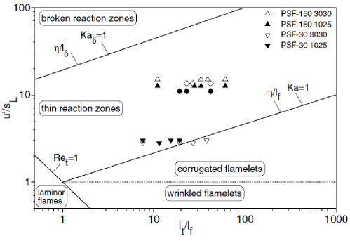
To characterize the turbulent flame the regime diagram classification of the flames based on measured integral scales at different positions is given in Fig. 3.2. This classification is common for premixed flames and indicates how the turbulence interacts with the thermal layer created by the chemical reaction. Herein the ordinate compares the flame propagation speed with the velocity fluctuation u' as representatives of characteristic velocity scales for the flame and the turbulence respectively. The abscissa relates the integral lengths scale to the flame thickness (typically in the order of 0.5mm), a large ratio indicates that the energy containing eddies are able to wrinkle the flame without modifying its local structure. The interal length scale herein has been obtained by two-point LDV measurements, where the spatial separation between the measurements locations was varied. The resulting normalized cross-correlation has been integrated to obtain values for at different locations. The location in the regime diagram obtained for the flame considered here indicates that a closed reaction surface - separating the fresh from the burnt gases - exists that is strongly wrinkled by turbulence, an information very important with respect to the combustion modeling.
The positions of the available experimental data are given in Fig. 3.3. Overall seven axial positions ranging from 1mm up to 120mm above the swirler exit have been considered. Available are:
- Velocity (mean and standard deviation) at 1, 10, 20, 30, 60, 90, 120mm measured by Schneider et al.[1] using Laser Doppler Anemometry
- Axial Velocity
- Radial Velocity
- Azimuthal Velocity
- Temperature and species (mean and standard deviation, case PSF 30 only) at 10, 20, 30, 60mm measured by Gregor et al.[2] using 1D Raman/Rayleigh scattering
- Temperature
- CO2
- O2
- N2
- CH4
- H2O
- H2
- Integral length scales obtained from tow-point statistics
- Frequency spectrum at x=1 mm, r=20 mm, for more information on integral time scales, ratio of longitudinal to transversal length scales at various locations we refer to Schneider et al.[1]
Description of the Experiment and Accuracy Considerations
This flame was characterized by laser Doppler velocimetry (LDV)[1] partly in combination with planar laser-induced fluorescence (PLIF) of hydroxyl radicals (OH) [3]. Therefore detailed information on means and variances of all velocity components, two Reynolds-stress components, length scales, time scales and power spectral densities exist. Combined LDV/OH PLIF provided even conditional velocities that were used similar to Frank et al.[4][5] to determine scalar fluxes at selected positions. In addition temperatures and main species concentrations were deduced from 1D Raman/Rayleigh spectroscopy. The following sections provide some information on the diagnostic methods.
Scalar field measurements by Raman/Rayleigh Spectroscopy
For multi-scalar 1D Raman/Rayleigh measurements an optical setup evolved from Geyer et al.[6] was used. The measuring system consisted of a cluster of four frequency-doubled Nd:YAG lasers that were fired sequentially with a pulse-to-pulse separation of 100 ns. Each of the 8 ns long pulses passed a single optical delay line to finally produce a 400 ns long pulse sequence with an energy content of 1.2 J at 532 nm. This pulse sequence was focused by an f=1100 mm lens into a 3.74 mm long probe volume. The resulting beam diameter was approximately 400 μm over the entire probe volumes length avoiding optical breakdown.
Raman and Rayleigh scattered photons were collected at the same side at 90 by a low f/# (f/#=2.0, open diameter 150 mm) custom-designed achromatic lens (Linos). At the image side Raman signals were focused onto the entrance slit of a Czerny-Turner type imaging spectrometer (Spex, f=270 mm) using a second custom-designed achromatic lens with an f/# of 4.0 matched to the spectrometer. Raman signals were spectrally dispersed (5.88 nm/mm) and detected using a backside-illuminated low-noise CCD camera (Roper). To allow for single-shot measurements and suppression of spurious light the Raman-CCD was gated by a mechanical shutter assembly (10s long gates). Binning in spatial direction resulted in 12 adjacent Raman probe volumes (310 x 400 x 400 μm3).
In front of the spectrometer Rayleigh signals were spectrally separated by a custom-designed long pass filter (Barr) with a steep cut-off between 540 and 550nm. Rayleigh signals passed an interference filter (532 nm, FWHM 10 nm) in front of an electron-multiplied thermo-electrically cooled CCD (Andor). Higher Rayleigh signal intensities allowed for less binning in beam direction resulting in an improved pixel-resolution of 77.5 x 400 x 400 μm3. Correct camera matching was confirmed by evaluation of Raman/Rayleigh data measured within a well-known laminar non-premixed jet flame.
Raman and Rayleigh single-shot data were evaluated by an iterative procedure based on a spectral fit of the ro-vibrational Raman bands. For more information regarding the data post-processing we refer to Gregor et al.[2].
Evaluation of single-shot Raman/Rayleigh spectra yielded local information on instantaneous temperature, equivalence ratio and mole fractions for each chemical component. As temperatures were sampled with 77.5μm resolution in beam direction, effective Rayleigh cross-sections deduced from the Raman-determined local species concentrations with 310μm resolution were interpolated linearly. Concentration levels of CO, however, were below 1% and therefore too low to be accessible by the present single-shot Raman-setup.
If not stated otherwise, 500 single-shots were recorded at each location. The 3.74mm long probe volumes overlapped by 0.6mm when shifted stepwise in radial direction. Radial profiles were recorded at axial heights of z=10; 20; 30 and 60 mm (limited by partial blocking of the detection optics for z¡8mm and dust particles entrained from the ambient for z>470 mm). Experimental uncertainties were quantified by calculating the relative fluctuations of temperature and concentrations from 200 single-shots recorded in a stationary lean premixed flat flame ( ϕ=0.8; except CH4) and in an isothermal flow (290K in a 22/78 CH4/air-mixture). Accordingly, the single-shot precision for the temperature determined by Rayleigh scattering was 0.2% at room temperature and better than 0.4% in the flat flame at 1970K. The single-shot precision for the concentrations were about 1.0% for CH4 and 1.1% for N2 at room temperature. In the flat flame with ϕ = 0.8 the fluctuations were for (X=0,72) for CO2 (X =0.08), 25% for O2 (X=0.04) and 9% for H2O (X=0.15) resulting in a precision of 10% for ϕ. CO and H2 are minor species and therefore the accuracy was lower.
Laser Doppler Velocimetry (LDV)
A fiber-optic LDV-system was used in backscatter mode. A mixture of MgO and ZrSiO4 served as seeding material. This choice was motivated by its thermal stability and small slip. Point-wise two perpendicular velocity components were measured simultaneously along various radial profiles to achieve mean velocities and higher order moments of axial, radial, and circumferential velocities. For the evaluation of mean values and fluctuations roughly 10,000 events were sampled. The overall error for the experimental data is estimated to be within 3% for the mean values and 7% for fluctuations. In direction of the laser light propagation the spatial resolution was 1.0 mm, perpendicular to light propagation approximately 0.075 mm.
In addition to the statistical moments, two-point measurements at highest sampling rates monitoring the instantaneous axial velocity component at two measurement locations simultaneously were performed to receive time-series. While one LDV measurement location was spatially fixed the second was moved. The displacement between both measurement locations was varied in positive and negative axial as well as radial directions to receive longitudinal and lateral correlations, respectively. These measurements were conducted at different locations within the flow field.
Cross- (evaluation of two-point-LDV) and auto-correlation functions (evaluation of single LDV-points) were deduced from these time-series using the fuzzy slotting technique, local normalization and transit time weighting[7]. By integration, this spatial/temporal information was used to estimate length/time scales (L11 and T11). Notice, that by positive and negative displacement in axial and radial directions, four different length scales were obtained: longitudinal length scales L11,+x, L11,-x and transversal length scales L11,+r, L11,-r. Time scales, however, were estimated from temporal auto-correlations obtained from single-point-LDV. Using the auto-correlation only, the E11 component of the power spectral density has been deduced by Fourier Transformation, respectively[8][9] .
For investigation of swirling flows spatial correlations are used to deduce turbulent length scales only. For the Fourier Transformation of the spatial cross-correlations the number of sampling points was too low. Therefore temporal auto-correlations are used instead and consequently one-dimensional power density spectra are obtained in the frequency domain. The performance of the optical setup and the data evaluation procedure a checked against a non-reacting turbulent jet of diameter d=8mm. For more details we refer to Schneider et al.[1].
Data Files
To obtain technical drawings or the experimental results in ASCII format please contact Prof. Dr. rer. nat. habil. Andreas Dreizler.
References
- ↑ 1.0 1.1 1.2 1.3 C. Schneider, A. Dreizler, J. Janicka, Flow, Turbulence and Combustion 74 (2005) 103–127.
- ↑ 2.0 2.1 M. Gregor, F. Seffrin, F. Fuest, D. Geyer, A. Dreizler, Proceedings of the Combustion Institute 32 (2009) 1739–1746.
- ↑ A. Nauert, A. Dreizler, Zeitschrift fr Physikalische Chemie 219 (2005) 635–648.
- ↑ J.H. Frank, P.A.M. Kalt, R.W. Bilger, Combustion and Flame 116 (1999) 220–232.
- ↑ D. Most, F. Dinkelacker, A. Leipertz, Proceedings of the Combustion Institute 29 (2002) 2669–2677.
- ↑ D. Geyer, A. Kempf, A. Dreizler, J. Janicka, Combustion and Flame 143 (2005) 524–548.
- ↑ H.R.E. an Maanen, H. Nobach, L. Benedict, Measurement Science and Technology 10 (1999) L2–L7.
- ↑ S.B. Pope, Turbulent Flows, Cambridge University Press, 2000.
- ↑ C. Schneider, Ueber die Charakterisierung von Turbulenzstrukturen in verdrallten Stroemungen, Ph.D. thesis, TU-Darmstadt, 2003.
Contributors: Guido Kuenne (EKT), Andreas Dreizler (RSM), Johannes Janicka (EKT)
EKT: Institute of Energy and Power Plant Technology, Darmstadt University of Technology
RSM: Institute Reactive Flows and Diagnostics, Center of Smart Interfaces, Darmstadt University of Technology
© copyright ERCOFTAC 2011


