Description AC2-08
Premixed Methane-Air Swirl Burner (TECFLAM)
Application Challenge 2-08 © copyright ERCOFTAC 2011
Introduction
The TECFLAM swirl burner is designed to investigate essential features found in industrial lean premixed combustors. An extensive set of measurements obtained by advanced laser-diagnostics exists to:
- Give insight into the underlying physics to gain a deeper understanding of the relevant phenomena
- Build a database well suited for CFD validation
Validation data exists for the reacting and non-reacting cases using the same velocity boundary conditions to allow for a separate assessment of the applied turbulence model and combustion model.
Relevance to Industrial Sector
This test case features some important properties which can already be found in current combustors and will become of increasing importance in the future. These are:
- Swirl stabilization
- Premixed flame
- Lean combustion
The swirl stabilization is common practice in gas turbine combustors which allows the design of a very compact premixed flame with a high power density. Regarding the pollutant formation (such as the emission of nitric oxides, NOx) lean premixed combustion is of increasing importance in many industrial applications (such as land based gas turbines [#Xbiagioli_stabilization_2006 Biagioli] ([#Xbiagioli_stabilization_2006 2006]), aero-engines [#Xlazik_development_2008 Lazik et al.] ([#Xlazik_development_2008 2008]) and automotive engines [#Xzhao_automotive_1999 Zhao et al.] ([#Xzhao_automotive_1999 1999])) due to the lower peak temperature when compared to non-premixed systems. Contrary to industrial applications this burner operates under atmospheric conditions (temperature = 300 K, pressure = 101325 Pa).
Design or Assessment Parameters
The parameters to validate CFD simulations are radial profiles at different axial positions downstream from the nozzle exit. These are:
- Velocity
- Temperature
- Major species
Furthermore the frequency spectrum based on the autocovariance has been measured to identify the precessing vortex core (PVC), a large coherent structure present under isothermal conditions.
Flow Geometry
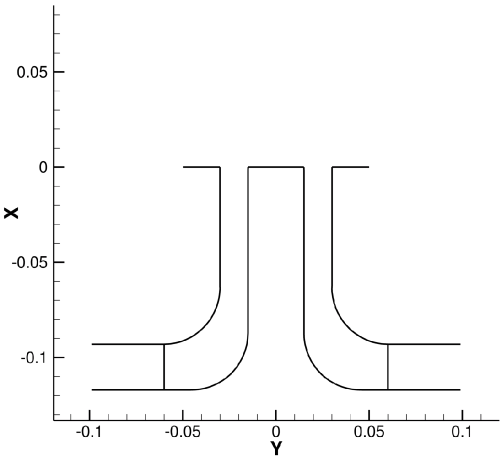
The nozzle consists of a 15-mm wide annular slot surrounding a 30-mm diameter, water-cooled bluff-body. The bluff-body temperature was stabilized at 353 K to avoid water condensation. Swirl was generated by a movable block. The nozzle was placed concentrically inside a co-axial airflow 600 mm in diameter. As illustrated in Fig. 2.1, the air enters the configuration from the bottom where methane is injected using a perforated ring line. Then the methane-air mixture is deflected by 90 degree to enter the radial and tangential channels (see Fig. 2.2) where the swirl is generated. Hereafter the fuel moves upward again, passes the annulus around the bluff-body and enters the unconfined section.
Flow Physics
The main flow parameters are:
- The bulk velocity of the methane-air jet issuing from the annulus around the bluff-body: u ≈ 5 m/s (case 30 KW), u ≈ 21 m/s (case 150 kW), (Ma << 1)
- The Reynolds number based on the bulk velocity and the hydraulic diameter (Dh = 30mm): Re ≈ 10, 000 (case 30 kW) , Re ≈ 42, 000 (case 150 kW)
- The swirl number which represents the ratio of azimuthal and axial momentum at the nozzle exit: S = ∫ RiRa(uw + u′w′)r2dr ∕ D h ∫ RiRa(u2 + u,2)rdr ≈ 0.7
- The flame, which stabilizes by the recirculation of hot gases above the bluff-body, has a thermal power of 30kW and 150kW respectively and covers the range of 1 < Ka < 4 and 4 < Da < 20 (Ka= Karlovitz number, Da=Damkoehler number) which leads to the regime diagram classification of a thickened wrinkled flame.
- The equivalence ratio of the methane-air mixture: ϕ = 0.83 (case 30 kW), ϕ = 1.0 (case 150 kW)
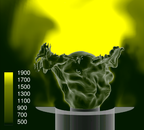
To provide an impression of the flow field Fig. 2.4 shows time averaged streamlines of the isothermal case to illustrate the expansion of the velocity field right after the nozzle exit and the formation of the central recirculation zone above the bluff-body. To give an illustration of the flame stabilization in the shear layer above the bluff-body and the intense flame turbulence interaction a snapshot of the reacting case simulation is shown in Fig. 2.5.
Contributors: Johannes Janicka (EKT), Guido Kuenne (EKT), Andreas Dreizler (RSM)
© copyright ERCOFTAC 2011


