Abstr:Underexpanded jet
Free Flows
Underlying Flow Regime 1-01
Abstract
The complex nature of turbulent fluid flow, in realistic applications, is usually a combination of many different underlying flow processes. One aspect of QNET-CFD is to identify all these important component flows, and subject these, individually, to scrutiny. The lessons learnt to date on modelling such flows, including meshing, turbulence modelling, and boundary conditions, will then be documented.
A CFD practitioner, having identified the underlying flow processes that shape their own real application, will be able to refer to (the appropriate combination of) these documents and gain understanding on the current knowledge of modelling the underlying physical effects, and hence, be in a good position to apply a high quality CFD methodology from the outset.
This document focuses on the particular underlying flow regime (UFR) of the turbulent, under-expanded, jet formed from releases of a gas from high-pressure sources, and considers only its initial expansion, by means of a complex shock structure. The subsequent effects, including jet impingement, or the jet‘s far-field dispersion, are considered elsewhere in QNET-UFR documentation.
The under-expanded, axisymmetric, free jet is perhaps one of the simplest flows which comprises both shock-wave containing compressiblity effects and turbulent mixing. It is a flow seen in many practical applications, including jets from propulsion systems (especially in aerospace applications), and releases (deliberate or accidental) from high pressure pipeline/storage facilities.
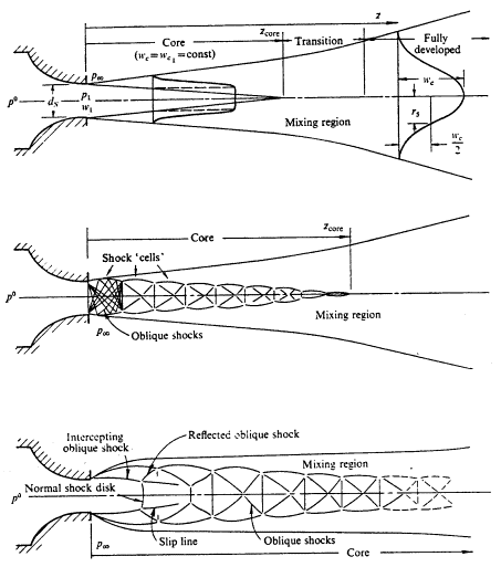
The profile of the jet, during its initial expansion phase, is primarily dependant on the pressure ratio between the reservoir stagnation conditions (P0) and the ambient pressure, (Pa). This is neatly described by Donaldson and Snedeker (1971), from where Figure 1 has been taken. A jet may be categorised into one of three types :
1. A subsonic jet, when 1.0 < P0/Pa< 1.89 , as illustrated in the upper plot in Figure 1. Here the pressure everywhere in the jet, including at its throat pressure, P1, will be equal to the ambient pressure, Pa. The jet is characterised by a potential core, surrounded by a mixing region. The radius of this potential core decreases to zero with increasing downstream distance, with the core not existing beyond zcore downstream. Beyond this point, the jet goes through a transitional phase as it continues to expand (as the velocity decays, in order to conserve axial momentum), and will eventually reached a fully developed, self-similar, state.
2. A moderately under-expanded jet, when 2.08 < P0/Pa< 3.85, as illustrated in the middle plot in Figure 1. If the pressure of the jet is higher than the critical (sonic) pressure, shocks begin to be formed at the nozzle exit, and the nozzle pressure, P1, will be higher than ambient; in the range 1.1 < P1/Pa< 2.0. The jet expands to ambient pressure though a series of oblique shock waves (or shock diamonds). The boundaries of what was the potential core in the above (subsonic) case are now characterised by the outer boundary of the shock cells, outside of which, the pressure is in equilibrium with ambient and mixing can take place. Downstream, beyond the range of this core, the jet becomes entirely subsonic, and can be assumed to expand as would a free jet.
3. A highly under-expanded jet, when P0/Pa> 3.85, is characterised by the presence of a Mach disk, and is illustrated in the lower sketch in Figure 1. The increased pressure in the reservoir results in the structure of the first shock cell changing. The rapid expansion along the jets centerline produces a very low axial pressure, and the recompression towards the end of the first cell exceeds the limiting case for the oblique shocks. A normal shock wave is therefore formed, (a Mach disk) a short distance downstream of the nozzle. Upstream of the Mach disk, the flow is supersonic, downstream it is subsonic. The nozzle pressure will now be higher, P1/Pa > 2.0. This profile will remain if the pressure is increased further, and may result in additional axial shock disks, as the subsonic flow downstream of the first shock is rapidly accelerated, and a second axial shock disk may be evident when P1/Pa > 4.0
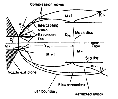
More detail of the shock structure in this initial cell was described by Crist et al. (1966), from where Figure 2 has been taken. An expansion fan forms at the nozzle exit, out towards the free pressure-boundary of the jet, and these are reflected as weak pressure waves, which join to form the intercepting shock wave. The flow in the jet core is clearly supersonic, as is the flow outside this intercepting shock, although of a lower Mach number. Just downstream of the Mach disk, the flow will be subsonic on the jet axis, though the flow outside of the intercepting shock remains supersonic. A triple point is formed where the Mach disk, intercepting shock, and reflected shock meet. Both the distance to this Mach disk, and its radius, can be expected to increase with increasing Mach number.
In this document, it is the latter two cases that will be studied – namely the cases of the moderately- and highly- under-expanded jets.
Contributors: Chris Lea - Health & Safety Laboratory


