Evaluation AC6-15
Vortex ropes in draft tube of a laboratory Kaplan hydro turbine at low load
Application Area 6: Turbomachinery Internal Flow
Application Challenge AC6-15
Evaluation
COMPARISON OF TEST DATA AND CFD
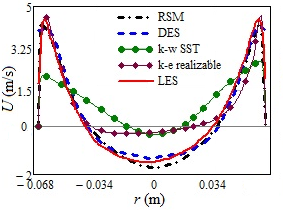
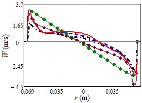
We present first a summary of the performance of various URANS models on a typical RANS grid of 2M nodes and compare with the LES on 6M and DES on 2M grid for the low part-load of ≈ 0.4. All RANS calculations were performed in unsteady mode. The time-averaged streamline patterns and colour contours of the fields of the vertical velocity in Fig. 7 clearly show that the RSM, DES and LES all give very similar results; whereas the linear eddy viscosity models (LEVM) show quite a different and, as shown below, erroneous flow pattern. This is substantiated by a quantitative comparison with experiments of the profiles of the axial and tangential velocity components and the rms of their fluctuations at the 3 mm cross-section, Figs 8 and 9. It is noted that the LES on the 6M grid reproduced best the experimental data, but the DES and RSM (both using the coarse, 2M grid) show also good agreement with the measurements. Since the DES employs LES in the flow bulk, it is likely that the LES would also reproduce well the helical vortex pattern on the 2M grid provided the near-wall region (with the average y+1,aver = 9.0) is treated by some wall-function, or using a near-wall RANS approach as practiced by DES. This option was not tested here since, as already stated above, the near-wall resolution on the 2M grid is far too coarse for a proper LES. In contrast, both EVMs notably failed, as shown by typical (unphysical) solid-body profiles of the tangential velocity and a wrong recirculation pattern. Moreover, the k-ε realizable and k-ω SST, LEVMs on the 2M grid could not maintain the unsteadiness, most probably due to excessive numerical diffusion that suppressed the natural instabilities, and resulted in stationary solutions failing to capture the twin rope precessing structures.
| k-ε realis. (2M) | RSM (2M) | DES (2M) | LES (6M) |

|

|

|

|

| |||
| Figure 7: Time-averaged vertical velocity field and streamlines in vertical symmetry plane. The colour denotes the velocity magnitude. | |||
| (a) | (b) |
 |

|
| Figure 8: Axial (a) and tangential (b) velocity component in the draft tube diffusor at 3 mm behind the cone, obtained by different turbulence models. Grids: (U) RANS and DES 2M, LES 6M. | |
The same prediction quality and trends are observed in the cross section located at 53 mm below the runner
(Fig.7, red line) as shown by the velocity profiles and their fluctuations in
Figs. 10 and 11. Due to the lack of experimental data at this cross-section we cannot verify the computational data. However, it can be seen that just as in
Figs. 8 and 9 for the cross-section of 3 mm, the RSM and DES models are in good agreement with the reference LES results, whereas the results obtained by the two linear EVM models differ significantly showing the same shortcomings as in
Figs. 8 and 9.
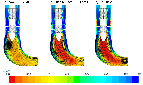
However, using a finer grid of 6 M notably improved the performance of the two LEVMs. This time the URANS computations maintained the unsteadiness throughout the whole computations and captured better the characteristic time-averaged streamline pattern and the associated mean velocity profiles, as illustrated in Fig. 12 (here shown for the k-ω SST model), comparable to RSM and DES on 2M in Fig. 7.
As seen in Fig. 12, the URANS (k-ω SST model) computations on 2M grid resulted in a steady solution which differs from those of LES (but also from the k-ε realizable model, Fig. 8), whereas the same model on the 6M grid produced unsteady solutions, which after averaging, come much closer to the reference LES pattern.

|
| Figure 12: Time-averaged vertical velocity field and streamlines from (U) RANS EVMs compared with LES. |
Figure 13 confirms the above by comparison of the mean velocity and turbulent kinetic energy with the measurements. A striking consequence of the failure of LEVMs on the coarser grid is seen in the profiles of the total (resolved plus modelled) kinetic energy (Fig. 13 bottom left). The failing to retain the unsteadiness and to resolve the fluctuating velocities led to compensation the resolved kinetic energy by an erroneous modeled turbulent stress and kinetic energy field.
Vortical ropes and pressure pulsations
Precession of the vortex core occurs under partial load (in the turbine model here considered at a discharge rate of 0.2 – 0.85 of the optimal value), where the flow has a considerable residual swirl. Vortex breakdown in such a flow leads to the formation of a recirculation zone (see Fig. 12) at the flow axis and the rotation of the corkscrew vortex rope (often visible by local evaporation or / and dissolved air) around it. Figure 14 shows selected snapshots of the typical vortex ropes and their structures after the runner, captured by different models and compared with experimental visualization of Skripkin, Tsoy, Shtork, & Hanjalić, (2016). The ropes are identified by the instantaneous isosurfaces of a selected value of pressure.
For practice, whether design or operation, it is vital to know the characteristic parameters of the pressure pulsations, primarily their intensity (especially the maximum amplitudes) and frequency. Since for the evaluation of these parameters the industry relies now more and more on CFD computations, using most often licenced CFD codes, it is essential to know a priori which model and method can be relied upon to deliver this information. To this purpose, in Fig. 15 we compare the calculated and measured pressure fluctuations.
The experimental pressure recordings are available from the measurements at discrete points in the middle of the draft tube cone and flush with the wall (4.5 cm below the swirler, Fig. 2).
Figure 15 (left) shows that the LES on the 6M grid, the DES (not shown) and the RSM on the 2 M grid return well the character of the pulsations and the measured maximum peak-to-peak amplitude of 9.57 Pa: the LES signal is almost indistinguishable from the experiment with the peak-to-peak value of 10.1 Pa, whereas the RSM gives a somewhat smoother recording, but with the right frequency and the maximum amplitude of 9.1 Pa. The latter finding is in a sense surprising, because it was previously considered by some researchers that the RSM usually returns lower amplitudes. In contrast, the LEVMs (on the finer grid of 6M), despite maintaining the unsteadiness, significantly underestimate the pressure pulsations, e.g. the URANS SST model gives a maximum peak-to-peak amplitude of only 4.2 Pa.
Thus, one of the main findings of the present research is the evidence that the second moment closure (Reynolds-stress model, RSM) even at the basic level (e.g. linear model of the pressure-strain correlation) and on a relative coarse gird (2M cells) is sufficiently receptive and sensitive to strong flow unsteadiness associated with vortex ropes and precessing vortex cores and can be used to estimate the level of the pressure pulsations in hydroturbine draft tubes.
Next to the amplitude, it is also important to know the frequency of the pressure pulsations, especially to identify the values associated with the dominant vortex structure, to avoid the potential resonance with eigen frequencies of the turbine and its equipment. A comparison of the measured and calculated frequency spectra is shown
in Fig. 15 (right).
As noted earlier, the twin rope structure in the draft tube immediately behind the runner consists basically of two precessing helical vortices, which apparently have somewhat different frequencies. This is seen in the
measured spectra (Fig. 15 right)
which indeed have identifiable peaks at frequencies of 13.88 and 16.5 Hz corresponding to a more or less intense helix respectively. The LES seems to capture well the double-frequency character of the spectra with peaks at 14.36 and 16.22 Hz respectively, close to the experimental values, though indicating also some stronger activities at about 25 and 30 Hz, which are not visible in the experimental recording. The RSM spectra look similar to LES with several peaks, the basic ones believed to correspond to the twin vortex rope being at frequencies of 14.38 and 19.2 Hz. Interestingly, for the locations considered (corresponding to those of wall pressure sensor points) neither the experiment nor any of the computations detected visibly the frequency corresponding to the runner blade rotation speed of 40.5Hz.
Contributed by: A. Minakov [1,2], D. Platonov [1,2], I. Litvinov [2], S. Shtork [2], K. Hanjalić [3] —
[1] Institute of Thermophysics SB RAS, Novosibirsk, Russia,
[2] Siberian Federal University, Krasnoyarsk, Russia,
[3] Delft University of Technology, Chem. Eng. Dept., Holland.
© copyright ERCOFTAC 2019


